Posts

Advantages and Disadvantages of Wave Energy

Image
Advantages of Wave Energy 1) Renewable Similar to most renewable energy sources, wave power is also renewable. Since this energy source ultimately comes from waves crashing upon the shores of many countries near the populated coastal regions, it will not disappear. 2) Environment Friendly Creating power from wave energy comes without the emission of harmful green house gases, waste, and pollution. 3) Small Footprint A wave power plant occupying less than half square mile in the ocean would generate more than 30 MW of wave power – the equivalent of nearly 20,000 US homes. 4) Reliable Wave energy is a very reliable source of energy because waves are hardly interrupted and almost always in motion comparing to solar and wind. It is a fact that the amount of energy that is produced and transported through the waves does vary year to year and from season to season. However, energy production is never going to stop. 5) Predictable Wave power is easily predictable and can be used to calculat...
How to improve steam generation, distribution and recovery can help a plant to increase its steam system efficiency by as much as 20-30%

Image
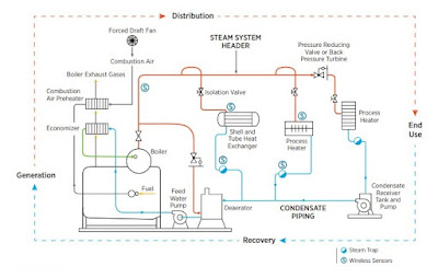
  Common areas for energy savings opportunities are steam generation, distribution, end use and recovery. This article outlines some typical energy efficiency measures. Demand reduction A plant’s boilers may be producing more steam or steam at a higher pressure than is necessary for the end uses. Understanding process requirements is especially important when downstream improvements, such as insulation and increased condensate return, are implemented. Lower losses translate into changes in steam production. A case study was conducted that a process engineer determined that a steam header pressure of 125 psig was no longer necessary due to changes in some of the plant’s processes. A team of personnel from the maintenance, utilities and production departments evaluated the feasibility of reducing the header pressure and decided to incrementally decrease header pressure, while monitoring the effects of this change on system performance. The pressure was reduced twice, first to 115 psi...

Definitions of MAWP, MAP, MOP, Design Pressure, Hydrotest Pressure, Burst Pressure, Working Pressure and more

Image
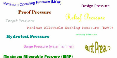
  Maximum Allowable Working Pressure  (MAWP) - maximum gauge pressure permissible at the top of the equipment in its operating position for a designated temperature (e.g. maximum pressure that the weakest component of the system can handle). Note: the maximum allowable working pressure is the basis for the pressure setting of the pressure relief devices that protect the equipment. Maximum Allowable Pressure  (MAP) or  Maximum Allowable Operating Pressure  (MAOP) - maximum pressure at which the equipment may be operated under; in another word, it is the maximum pressure in the new and cold condition of the equipment. Maximum Operating Pressure  (MOP) - maximum operating pressure is the maximum pressure that equipment can be operated at below its high pressure alarm or shutdown, or 95% of MAWP, whichever is lower. Burst Pressure  - Burst pressure is the maximum internal pressure that a pressurized component such as piping or joint or tube can withst...

What is the Rich/Lean Amine Loading and what is the appropriate value for them?

Image
  Amine loading is calculated as the mole ratio of acid gas to the solvent. Rich amine loading (RAL) is referred to the acid gas absorber bottoms liquid which is rich in acid gas and similarly Lean amine loading (LAL) is referred to the bottom of the striping column which is lean in acid gas. Usually, the amine loading measurement is very difficult in the field or in a lab, so plant simulations are used to determine the RAL and adjust the amine circulation rates and concentrations to meet desired results. Generally, RAL is kept under the value of 0.40; due to several detrimental effects, especially in an all CO2 acid gas system. These effects may include higher corrosion rates, higher temperature bulges within the Contactor and lower recovery of the acid gases, due to slower reaction kinetics and capacity. Generally, the measurement of Lean Amine Loading (LAL) is relatively easy and reliable, though simulation results can still be used to check the collected data. LAL values will v...

What is the criterion for selecting operating pressures for multistage separator systems?

Image
Operating pressures of multistage separation systems can very across the wide range. The maximum OP for of a separator will be no higher than sales gas pressure accept in the case of gas lift requirement where in the pressure is higher than sales gas pressure. In case of intermediate stages the gas will need compression therefor optimization of intermediate separator can be derived from equation below: R = (P d  / P s ) 1/n where: R = Ratio per stage P d  = Discharge pressure P s  = Suction Pressure n = number of stages The minimum pressure for the lowest pressure stage can be between 20 to 50 psig. This pressure should be set such that there is enough suction head for the downstream pumps.

Process Analyzer Sample Systems

Image
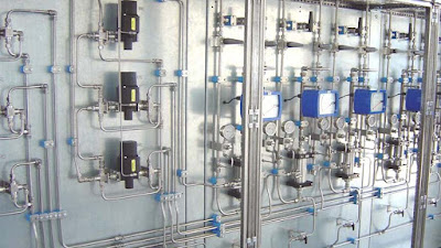
  Process Analyzer Sample Systems are common to almost all process (on-line) analyzer installations, but often overlooked or not addressed adequately. They are usually 80% of the challenge (and support requirements) of an analyzer system. Several elements are crucial to consider in design, installation, calibration, and operation of any sample systems. Complete (as much as possible) stream data is essential in starting design. Maintaining sample integrity is important to meet the required accuracy specifications. The system must be protected from a corrosive sample and a harsh environment. Safety must be considered with corrosive, toxic, or high pressure samples. The analyzer must be located, protected from the environment, so that maintenance can easily be performed, and with consideration of sample condition(i.e. not a low point if sample dew point could be a problem). Calibration needs to be addressed depending on whether sample is a liquid or vapor and whether there is a lab me...

Tank Blending

Image
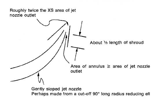
Figure 1 - Blending can be improved by a shrouded blending nozzle system because the jet nozzle educts a large quantity of surrounding fluid. This document discusses a simple low cost tank blending method. It is referred to as a shrouded blending nozzle system, and it works quite well. The shroud causes the jet nozzle to educt a large quantity of surrounding fluid, improving blending. A simplified diagram of the nozzle portion is shown in figure 1 above. Make the nozzle point upward at an angle such that a straight line projected from the nozzle would hit the liquid surface 1/2 to 2/3 of the way across the tank diameter. The idea is to promote top to bottom turnover. However, tilt the nozzle slightly to the left to promote a slight swirl effect. Aim the nozzle at a point about 1/3 of a radius off-center. The following rules of thumb apply primarily to the situation where a final tank requires blending after, and perhaps during, transfer from rundown tanks. Base tank size 10,000 barrels...

Quench Control - An advanced approach for temperature control

Image
  Quench control is used in closed loop refrigerant applications where cooling of the hot recycle gas stream is achieved by direct mixing of a cold multi-phase gas/liquid. The liquids used for quenching are already produced by operation of the refrigeration compressor, so a separate cooler is not needed. Also included is a cooler vessel and a quench fluid line for cooling; the quench fluid maintained in a liquid state through the entirety of the quench fluid line. Yet further included is a quench control valve disposed downstream of the cooler vessel to control a flow rate of the quench fluid routed therein. Also included is a refrigerant suction drum located downstream of the quench control valve and configured to receive the quench fluid from the quench fluid line, the refrigerant suction drum in fluid communication with at least one component for cooling. Figure 1 shows a piping schematic for quench control on the first side-stream of a four-stage refrigeration compressor. In it...