Process Analyzer Sample Systems
Process Analyzer Sample Systems are common to almost all process (on-line) analyzer installations, but often overlooked or not addressed adequately. They are usually 80% of the challenge (and support requirements) of an analyzer system. Several elements are crucial to consider in design, installation, calibration, and operation of any sample systems. Complete (as much as possible) stream data is essential in starting design. Maintaining sample integrity is important to meet the required accuracy specifications. The system must be protected from a corrosive sample and a harsh environment. Safety must be considered with corrosive, toxic, or high pressure samples. The analyzer must be located, protected from the environment, so that maintenance can easily be performed, and with consideration of sample condition(i.e. not a low point if sample dew point could be a problem). Calibration needs to be addressed depending on whether sample is a liquid or vapor and whether there is a lab method to verify composition.
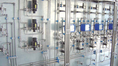
Sample conditioning and stream selection systems should be designed and assembled to provide representative process samples with a minimum lag time to each analyzer under conditions compatible with the operation of the analyzer. Sample systems should be designed to minimize the amount of process samples entering an analyzer house, thereby reducing hazard in the event of a leak. Sample systems should be designed and assembled to provide ease of maintenance, protection from hazards, troubleshooting facilities, and long-term reliability. Simplicity should be a prime design consideration.
Design Considerations
Sample conditioning systems should be designed to extract representative samples from process streams and transport samples to the analyzers with minimum lag time. The sample conditioning system should be designed to provide sample temperature, pressure and flow control with indication; filtration; and removal of entrained or condensed liquids from vapor samples as required for continuous operation of the analyzers. Special consideration should be given to sample streams for which temperature and pressure control is critical to maintain the dew or bubble point, or prevent polymerization. All tubing fittings and valves should be Swagelok, unless otherwise specified. Other manufacturers' fitting and ferrules are not to be interchanged. In addition to these general requirements and design considerations, the sample conditioning systems should incorporate the following specific design features:
- All process samples, except as noted, should be extracted with sample probes inserted through 3/4 inch, full-ported gate valves (gate valves by others). Sample probes should include a packing gland to allow removal and primary sample shut-off valve. The gate valve should have a red tag, "Do Not Close, Probe Thru Valve". Each field sample tap and return tap should have a pressure gauge.
- High pressure vapor samples (i.e., greater than 100 psig) should be reduces at the sample tap with a field pressure reducing station.
- Liquid samples not vaporized for analysis should be transported to the analyzer houses through a fast-flow bypass loop should be installed on the outside of the Analyzer House.
- Liquid samples to be analyzed as vapors should normally be vaporized at the sample tap with a field vaporizing pressure reducing station. However, samples not readily transported as vapors should be transported as a liquid to the analyzer house through a fast-flow bypass loop and vaporized at the Analyzer House.
- Sample transport lines requiring heat tracing should be self limiting type, electric-traced bundles or steam-traced and insulated bundles. Ground fault interrupters should be installed on all electrically traced bundles. Heat tracing using steam is preferred from a safety and reliability standpoint. Temperature must be below 80% of auto ignition temperature and should not exceed the "T" number.
- High temperature liquid sample transport lines (i.e., greater than 150 deg F) should be insulated for personnel protection.
- Sample systems for pH, conductivity analyzer, and other similar type analyzers should normally be located in the field with the analyzer sensor near the sample tap, unless otherwise specified.
- All sample systems installed inside the Analyzer Houses should include a shut-off valve to isolate the sample system from the sample transport line and a pressure indicator located upstream of the isolation valve. Where required (e.g. for field pressure reducing stations), pressure relief valves should also be located upstream of the isolation valve. Isolation valves and pressure indicators should also be utilized in fast-flow bypass loops installed on the outside of the analyzer houses.
- All sample systems should include facilities for extraction of lab samples, unless otherwise specified. Lab sample valves and connections should be located outside the Analyzer House and labeled as such.
- All indicators (pressure, temperature, and flow) should be sized such the indication is in the middle third of the scale under normal operating conditions.
- The pressure of process samples in contact with glass sample system components (e.g., flow indicators) should not exceed 100 psig unless otherwise specified. Glass components in contact with process samples capable of exceeding 100 psig should be protected by relief valves.
- All sample conditioning and transport systems should be designed to provide a maximum sample lag time to the analyzer of one minute, unless otherwise noted. In general,all sample systems should incorporate a fast-flow bypass stream to minimize sample lag time.
- Heated sample systems should be installed in steam-heated and insulated enclosures with temperature indication. Consideration should be given to the operation and maintenance of heated sample systems without causing sample condensation. Electrically heated enclosures and electrically heated vaporizing regulators may also be used.
- Heated sample lines within analyzer houses should be steam traced and insulated. Electrical tracing of the proper design is also acceptable.
- Sample systems, or component parts thereof, to be installed in the field should be completely assembled units.
The design and assembly of all sample systems should give proper consideration to logical and consistent organization and placement of component parts including low point drains, sloping of lines, dead-end pockets at junctions, contamination, etc.
Components
Sample systems should be designed and assembled using discrete components to facilitate convenient maintenance and/or replacement. Uniformity of component selection should be of prime consideration to minimize the stocking of spares and facilitate convenient substitution. It is generally prudent to follow facility standards.
Materials of Construction
All materials in contact with process samples should be corrosion resistant. In general, these materials should be stainless steel (type 316 preferable), glass, Teflon, Viton, or Kel-F. No copper silver bearing alloys should be allowed in contact with process samples.
The bodies of sample system components (e.g., filters, regulators, valves, fittings, etc) should be stainless (type 316 preferably, type 304 minimum). Where material than stainless steel is required (e.g., Teflon, Hastelloy, Monel, etc.) it should be specifically noted in the drawings. Sample tubing should be type 316, seamless stainless steel with a minimum 0.035 inch wall thickness.
Multi-stream Applications
Analyzer Systems requiring automatic and/or remote analysis of samples from multiple points should be provided with a sample stream switching system incorporated into the Sample System. Unless otherwise specified, sample stream selection should be accomplished with air-operated ball valves assembled in a double block and bleed configuration to prevent cross contamination of sample streams. In general, this configuration should utilize a three-way ball valve and check valve to provide double block and bleed. To indicate leakage, vapor samples should bleed to a low volume flow indicator. The arrangement and assembly of sample stream switching system should minimize dead volume and sample pockets. Individual sample conditioning should be provided for each stream such that maintenance of one stream does not affect the operation of any other stream.
A preferable method for handling multi-streams, especially liquid process streams, is to have a separate sample valve and a separate sample system for each stream. This method eliminates cross-contamination problems.
Calibration Sample Introduction
All Sample Systems should include provisions to introduce a calibration sample or extract a representative sample for laboratory analysis. Shut-off valves should be provided to isolate process sample and calibration sample streams. Where practical, automatic and/or remote calibration sample introduction should be accomplished in the same manner as sample stream switching, specified above. Automatic time-of-day calibration is especially recommended for gas chromatograph systems. If manual calibration is performed, then the introduction of calibration samples or extraction of lab samples should be accomplished through the operation of manual valves.
Effluent Sample Return, Vent and Drain
Direct venting of hydrocarbon and/or toxic vapors to the atmosphere is to be minimized. All effluent samples from relief valves, bypass streams, and analyzer streams containing hydrocarbon and/or toxic vapors should be returned to a low pressure collection point (either flare or first stage suction drum), if possible.
Analyzers monitoring process streams containing hydrocarbons should be operated under pressure to facilitate return of effluent samples. The sample system for the analyzer should provide samples at a constant pressure for stable operation.
Effluent vapor samples from chromatograph sample valves or leak detection bubbles that must be vented to atmospheric pressure should be routed to an atmospheric vent header and discharged to the atmosphere through a flame arrestor at least 5 feet above the analyzer house and 10 feet from the ventilation intake. Chromatograph columns and detectors can be vent directly into the analyzer house and not routed to the atmospheric vent header.
Effluent liquid samples from drains that cannot be returned to the process should be drained to the process water sewer in a closed system.
Shelters
All sample system enclosures designed to handle hazardous vapors or liquids (toxic or combustible) should be provided with an air or N2 purge system. The enclosures should be vented to a safe vent. The enclosure vent should be continuously monitored to detect the presence of hazardous materials. Sample handling systems designed to handle hazardous vapors or liquids should be mounted on the outside wall of an analyzer house to limit the total volume of hazardous material within a house. The total number of tube fittings or piping connections for hazardous materials within a house should be kept to a minimum.
Analyzers mounted in an analyzer house, and requiring H2 fuel for a hydrogen flame detector, will be mounted within a purged NEMA-4 enclosure. The enclosure vent will be piped to a safe vent or to ambient air. The H2 feed line to house will include a restricting orifice prior to entering the house. Tubing downstream of the orifice will not be greater than 1/8". The tubing connection from the restricting orifice to the instrument will be unbroken. Bored bulkhead fittings will be will be used for access through analyzer house walls, and the NEMA-4 enclosure. Any analyzer house or enclosure within which H2 is being used will include the use of a combustible gas detector mounted at the top of the house or enclosure.
Within an analyzer house in which N2 or other inert gases are used for purging, zeroing or as a carrier gas, an O2 deficiency analyzer will be installed for continuous monitoring of the house atmosphere.
Calibration and utility support gas cylinders should be located at grade level. All gas cylinders should be secured with a gas cylinder rack. Gas cylinder racks should be manufactured in accordance with OSHA regulations and the Compressed Gas Association's (CGA), although a properly sized relief valve may be substituted for the rupture disk.
Special System Considerations
Ambient air monitoring systems, designed to detect low concentrations of toxic gases should be designed to eliminate or inhibit sample component loses due to adsorption or absorption. Materials of construction should be specified based on tests conducted with calibration standards prepared at the concentrations levels being monitored. These tests should be conducted prior to specification and purchase of an ambient monitoring system. At a minimum, tests should include introduction of the standard through 100 foot of sample transport tubing at flow rates to be used for sample transport. Sample transport tests should also include the sample filters, sample cell, vacuum chamber, etc., and detector proposed to be used for the analysis. Tests will be conducted at ambient temperature, 250C and at elevated temperatures to at least 500C. Sample transport times, peak rise times and peak heights will be monitored and recorded to determine absorption and adsorption rates and loses.
All sample systems and analyzer installations should conform to the following electrical safety standards:
- NFPA496
- ISA Standards
Comments
Post a Comment