Renewable Energy from Green Waste using Fischer-Tropsch Process
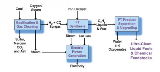
The Fischer-Tropsch (FT) process to convert green waste into renewable energy is a multi-steps chemical reactions in both coal liquefaction and gas to liquids technology for producing liquid hydrocarbons. The Fischer-Tropsch plants typically go through the following process of conversions.

Biomass feed consists of yard waste, tree trimmings, and scrap lumber. Biomass feed will be blended to provide a feed mixture for drying and gasification. Feed streams will be moved with a series of belt and screw conveyors. After blending, a mechanical screener will remove fines and a belt magnet will remove tramp ferrous metal. Following the belt magnet, a device will detect and reject non-ferrous metal. After screening, a grinder will reduce biomass feed chunks to 3" or smaller in preparation for drying. After grinding, a drying system reduces moisture from 40% to 12%, without releasing volatile organic compounds to the atmosphere. After drying, biomass feed is transferred to the gasifier.
The gasifier system consists of two fluidized beds with hot sand circulating between the gasifier and the combustor. Dried biomass from a feed hopper, hot sand from the combustor, and fluidizing steam are fed to the bottom of the gasifier. Heat from the sand converts biomass feed into a mixture of vapors containing primarily synthesis gas (H2 and CO), methane, tars, char, and ash. Vapors exit the gasifier into cyclone separators to separate char and entrained sand from the gas products.
Gasifier cyclone sand and char are sent to the bottom of the combustor where char is burned with air to reheat the sand. FT wax containing spent catalyst is fed to the combustor as supplemental fuel. Hot sand entrained in combustor flue gas is removed in cyclone separators and returned to the gasifier. Hot combustor flue gas is sent to the feed dryer to remove biomass moisture and through an Selective Catalytic Reduction (SCR) reactor to remove NOx. Cooled flue gas from the feed dryer enters a lime scrubber to remove SOx followed by filtration before venting to the atmosphere.
Syngas Conditioning
Syngas product from the gasifier is processed with enriched air in a partial-oxidation reactor to reform methane and tars. Enriched air is supplied from a vacuum swing adsorption unit and heated prior to the reactor. Hot syngas from the partial-oxidation reactor is quenched with water to reduce temperature. Quenched syngas is cooled in a steam generator while producing high-pressure saturated steam for power generation.
Syngas Cleanup
Cooled syngas next enters a water wash column to remove particulates, nitrogen compounds, and residual heat. Clean syngas is compressed and passes through a reactor which converts Carbonyl Sulfide to H2S. Clean syngas containing H2S is sent to a Sulfur Recovery Unit (Lo-Cat Unit) for sulfur removal.
Downstream from the cleanup system a portion of the syngas will be diverted to a Polybed Hydrogen pressure swing adsorption (PSA) unit to produce high-purity hydrogen for the product upgrading and FT catalyst activation. PSA unit tail gas will be compressed and cooled before blending in the fuel-gas system.
The main syngas stream is directed to the Fischer-Tropsch reactor where the syngas is contacted with an iron catalyst to produce hydrocarbons. Steam coils inside the FT reactor will maintain an isothermal reactor profile while generating MP steam. Heavy hydrocarbons (wax) will be removed from the FT reactor by use of dynamic settlers. The wax is directed to a secondary filtration unit and then to product upgrading for further processing. The overhead gas from the FT reactor will be cooled to condense out a middle distillate and a light distillate stream. The distillate is directed to a stabilization column before being sent to the product upgrading unit. Light oxygenates and water, generated in the FT reactor, will also condense from the overhead gas. The condensed water stream is separated from the distillate and directed to wastewater treatment. The uncondensed gas, or FT tail gas, is combined with any syngas that bypassed the FT unit and is directed to power generation.
In the upgrading section, light distillate from the stabilization column or from intermediate storage is hydrotreated to convert olefinic components into parrafins and to remove oxygenates. FT wax is directed to a hydrocracker where long hydrocarbon chains are broken to produce a diesel distillation range. Hydrocracking action also isomerizes the molecules to suppress the cloud-point (melting point) of the product diesel. The reactor products from the hydrocracker and unionfiner sections are directed to a stripper and distillation column where naphtha and diesel products are recovered. A heavy recycle stream is directed back to the hydrocracker.
Electricity for export and plant use will be generated by two generators. One generator will be driven by a gas turbine which consumes approximately 1/3 of the syngas produced. The second generator will be driven by a steam turbine which consumes high-pressure steam produced by the gas-turbine heat recovery steam generator (HRSG), syngas steam generator, and fired boiler. Boiler feed water for steam production will be produced from the available local recycled water.
Renewable Energy Case Study: A renewable energy plant converting 1000 TPD (dry) urban green waste can generate 600 BPD of Fischer-Tropsch fuels and 16.5 MW of export electricity. The feed consists of yard waste including leaves and grass; tree trimming including whole and shredded limbs; shredded construction and demolition waste lumber. The renewable energy plant will receive 2800 WTPD with a moisture content of about 40%. The feed stream will be received and stacked on a tipping floor. A manual sorting operation will remove the large metals and non-bio items that are not wanted in the gasification process. Afterward, blending and removal of tramp materials, the feed is shredded to <3” for feed to the drying system. The drying system is designed to reduce the moisture content of feed from 40% to 12%. The dried feed is sent to the gasifier. The synthetic gas that is produced in the gasifier in conditioned through a partial oxidation reactor (POX); then goes to syngas compression to boost the pressure for the Fischer-Tropsch (FT) unit. The gas goes to the FT unit which produces FT liquids from the syngas. The FT liquids run through the Honeywell UOP Technology's upgrading facilities to produce 466 bbl/day of "green diesel" or syngas and 166 bbl/day of Naphtha. The off gas from the FT unit, plus the steam generated in the previous processes goes to a power generation to produce 36.5 MW of electricity. Net export power is estimated at 16.5 MW.

Comments
Post a Comment